Planning a floor in the planner, from the tape measure to the tile count
· 11 min read
Step by step, what planning a floor with the planner actually looks like on a real flat: measuring, the outline, the joints between materials, patterns and the material count.
The flat is plastered and waiting for its floor: a living room with an open kitchen area, a hallway joining it to the front door and an entrance lobby right behind that door. The kitchen area and the lobby are going in 79 × 79 cm tile with a 2 mm joint, the living room and the hallway in 120 × 20.5 cm plank. On the architect's drawing that looks like four rectangles and two lines on a shopping list.
The drawing describes brickwork, though, and a floor is laid on plaster, so those two rooms have different dimensions. With a 79 × 79 cm tile a centimetre of difference can turn an unremarkable cut at the wall into a narrow strip, and it tends to show up on the day the material is already sitting on the pallet.
Dimensions from the drawing expire on the day the plasterer leaves the site
We start by measuring in the flat, with a laser meter or a tape. Every axis gets measured in three places: at one wall, in the middle and at the other, because walls are rarely parallel. The largest reading goes into the calculations, and recesses, door reveals and the width of the opening between the hallway and the living room get written down separately.
The readings land straight on a sketch on paper, with a number written against each wall. We sketch around the perimeter, because when it comes to typing all this into the planner the point is to read the numbers off one after another, without guessing which wall 412 belongs to.
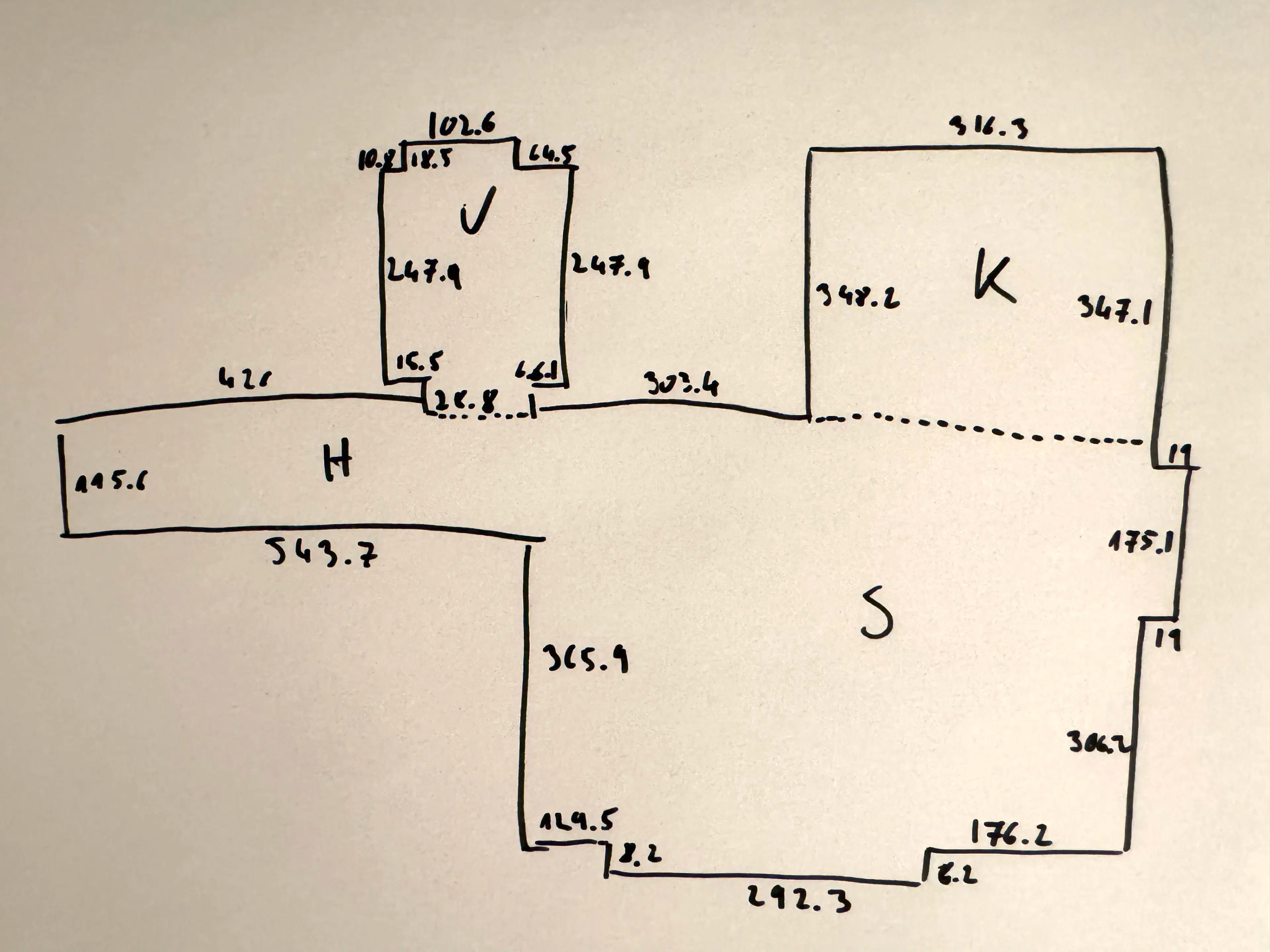
We draw the outline by eye and type the dimensions in afterwards

The whole floor area goes into the planner as a single surface, because the living room, the kitchen area, the hallway and the lobby make one continuous run of floor. The borders between materials come later, inside that outline.
The first way is the “Draw walls” tool . We click corner after corner and close the outline, deliberately roughly, because at this stage the shape is all that counts. Holding Shift keeps the line at 45° angles.
The second way builds the shape out of rectangles. With “Add surface” we drag a rectangle that merges with whatever is already on the plan, so the living room, the hallway and the lobby come out as three blocks running into one body. “Subtract surface” works the other way: it cuts out a column, a riser duct or a run of units we are not laying under.

We take the walls in order and lock the corners we are sure of
On the finished outline every wall carries its own length beside it. We click that number, type in the dimension from the sketch, and the wall moves to the length given. We set off from the wall at the top of the plan and go clockwise, because typing in a dimension moves the far end of the wall, which keeps us working on the part of the outline we have not described yet.
Next to the dimension field sits the “Keep right angles” switch, on by default. While it is active, the corner beyond the wall being corrected travels along so that a right angle stays a right angle. Plastered walls sometimes meet at a different angle, and then, for the one dimension being typed in, we switch it off.
The second safeguard is the corners. Clicking a corner offers “Lock corner” , and a locked corner cannot be dragged or pushed aside by a change to the neighbouring wall. We lock the ones that already agree, and further corrections then run in one direction instead of pulling apart work already done. With both ends locked the planner refuses to change the wall's length and says so outright, so a conflict between dimensions shows up immediately rather than two steps later.

The expansion joint marks the border between tile and plank
There is one outline and two materials, so we cut the floor where one turns into the other: where the kitchen area meets the living room, and at the way out of the lobby into the hallway. That is what the “Expansion joint” tool is for. We draw a line across the floor and the planner runs it out to the walls; Shift locks the angle the line runs at.
Two joints never cross. A line arriving at one that already exists stops there and forms a T, which is what turns a series of cuts into readable regions. The planner takes the width of the joint from the pattern's grout, 2 mm in our case, and the “Joint width (mm)” field in Settings changes it.
These lines have backing in the installation instructions. Egger lists the places where an expansion profile is compulsory: door thresholds, doorways, rooms that turn a corner, and any length or width over 10 m. The living room and the hallway form exactly that kind of turn, and the lobby ends in a doorway. The cuts we draw in the planner land where a trim strip is going to stand on site anyway.
An insert in the middle of the floor, a rectangle of a different tile in front of the kitchen for instance, is a job for the “Pattern within a pattern” tool. Once dragged, the rectangle can be turned.

The main pattern goes where the floor shows most
The second stage starts with the main pattern, because everything we do not describe separately will carry on from it. In this flat the main pattern is the tile in the kitchen area.
From the “Patterns” library we pick the Squares Pattern template and in its parameters set Piece Size to 790 mm and Gap Size to 2 mm. The gap is our grout joint and goes into the calculation together with the tile, so what the planner lays out on the floor is a module wider than the tile itself.
In the same panel we upload a texture, a photograph of the tile. On a grid of squares the image covers one repeat of the pattern and repeats with it, while the joint is drawn on top. The preview stops being a grid of lines and starts to look like a floor, which helps when deciding which way to run the layout.
Every region either follows the main pattern or gets one of its own
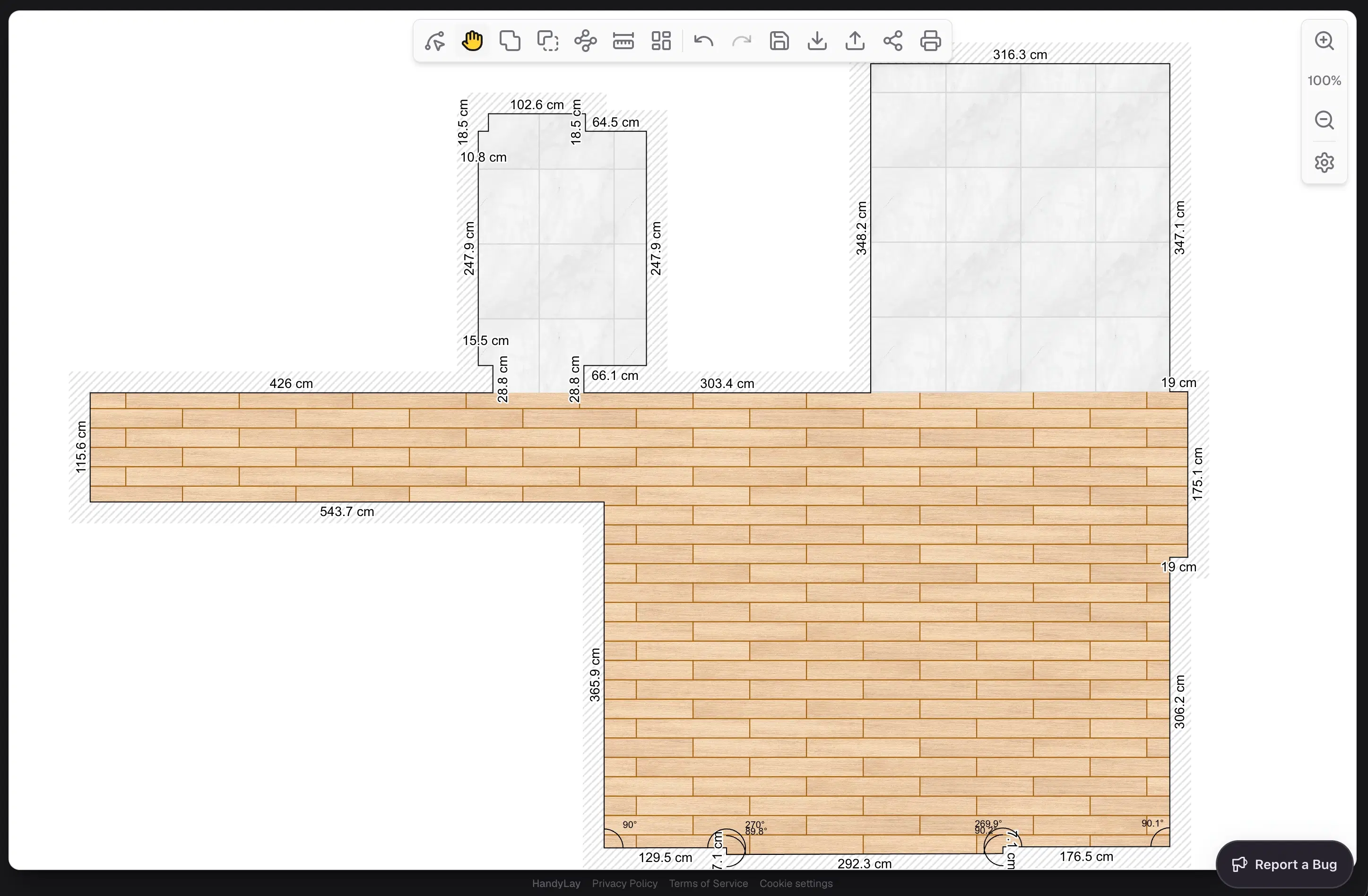
Once the floor is cut, numbered buttons appear on the toolbar, one per region. Clicking one opens a dialog with a single checkbox: “Carry on with the main pattern”. Ticked means the region lies in the same layout as the rest of the floor, with pieces crossing the joint without a shift. Unticking it detaches the region and gives it a pattern of its own, moved independently of the others.
For the living room and the hallway we untick it and choose the Bricks Pattern, with Piece Width 1200 mm and Piece Height 205 mm, our 120 × 20.5 cm plank, with the rows offset as the plank manufacturer's instructions say. On long pieces the texture behaves differently than on a tile: each plank gets its own fragment of the image, running along its longer side. One shared pattern for both rooms also means a plank crossing the doorway counts as one piece cut into two.
The lobby is the same tile as the kitchen area but a separate piece of floor with a starting point of its own, so it too gets a pattern detached from the main one. That decision comes back when the material is counted, because the planner counts every pattern separately, each with its own layout.
We nudge the pattern until the cuts at the walls stop grating
The pattern lands on the floor wherever the geometry puts it, regardless of how the room is seen. We drag it with the mouse and finish with the arrow keys, because one press of an arrow is a millimetre; holding the arrow repeats the move. When a region has a pattern of its own, the arrows move only that one.
Clicking a single tile or plank shows its cut: the dimensions of what is left after cutting and what fraction of a piece that is. That is how we check the edges visible from the doorway, before anything goes into the basket. The rule we set the starting point by is the same for tile and for plank, and the guide on where to start tiling describes it.
The numbers come out separately for each pattern
In the same dialog the planner gives a summary of the surface: how many pieces are needed, how many of them go down whole, how many need cutting, how many square metres of material that works out at and what percentage of it is waste. On a divided floor a breakdown by pattern comes with it, a piece count and an area against each.
Regions carrying on the main pattern count together, because that is one continuous run of laying. A region with a pattern of its own gets its own line, so the tile in the kitchen area and the tile in the lobby come out as two numbers even though we buy them together. We add them up before ordering, and only then add the spare the manufacturer asks for.
One more thing helps when reading the waste figure: the planner treats every offcut as waste and does not match offcuts to each other. With plank, some of the end pieces go back to the start of the next row, so the real usage in the living room will be lower than the percentage shown. With a 79 × 79 cm tile that difference is much smaller, because a cut from one wall rarely fits the other.
Where these numbers come from
- EGGER, installation instructions for laminate flooring with the JUST clic! system - expansion profiles compulsory at door thresholds, doorways, rooms that turn a corner and at any length or width over 10 m; an 8-10 mm expansion gap to every fixed element.
- The tool names and their behaviour come from the English interface of the HandyLay planner.